Outdoor Telecom Cabinet is an important device for carrying core telecom equipment in outdoors, and its heat dissipation capacity is a basic condition for the smooth operation of the entire system. However, during the long-term operation of this kind of projects, we found that the cooling capacity calculation for outdoor telecom cabinets was wrong, resulting in heat dissipation problems at telecom carries‘ outdoor sites. We believe that the issue of how much cooling capacity an outdoor telecom cabinet should be equipped with air conditioners is very clear to many manufacturers and telecom operator. However, problems often arise not because of theoretical calculations, but because of neglect of the actual deployment environment. and a series of problems caused by negligence in expansion management. This article will try to start from the perspective of cooling capacity calculation for outdoor telecom cabinet, focusing on issues that are easily overlooked during actual deployment, so as to help operator customers better understand How to Calculate Cooling Capacity for Outdoor Telecom Cabinet.
2.Understand Cooling Capacity of Air Conditioner on Outdoor Telecom Cabinet
2.1 What is Cooling Capacity and Its Key Assumption
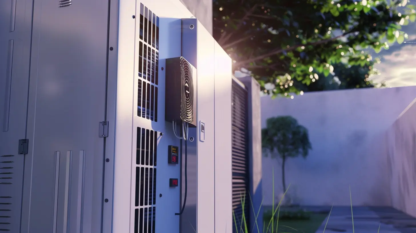
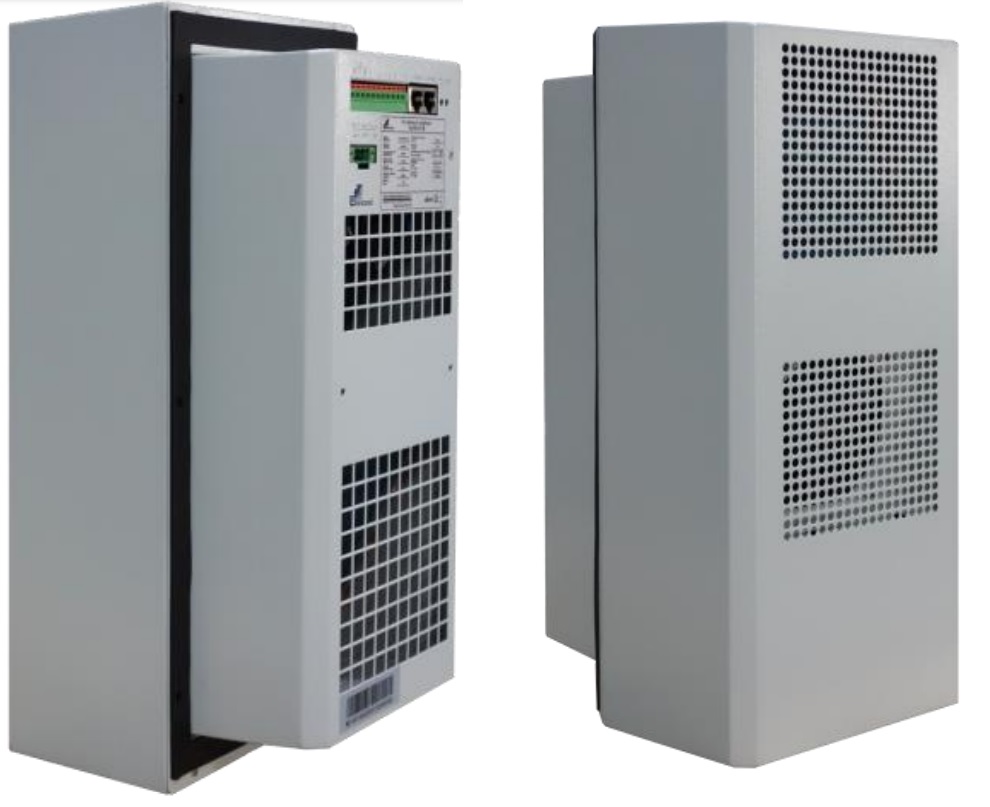
Typical 300W Cooling Capacity Air Conditioner
The picture above is a typical 300W Air Conditioner. There are also larger cooling capacities such as 600W, 1200W, 1500, 3000W, etc. This article will take this 300W Air Conditioner as an example to illustrate.
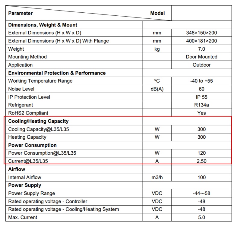
300W Cooling Capacity Air Conditioner Specifications
The table above is an example of the Cooling Capacity of this 300W Air Conditioner. You can find a row of parameters saying Cooling Capacity@L35/L35. From here we can draw two important messages:
(1) Max Cooling Capacity 300W This specification means that this air conditioner can take 300W of equivalent heat from the outdoor telecom cabinet out of the cabinet. (Although this statement is not particularly accurate, it is easy for everyone to understand and apply) (2) @L35/L35 The first L35 refers to when the temperature inside the cabinet is 35℃, and the second L35 refers to when the ambient temperature is 35℃. It can be seen that the 300W cooling capacity is based on this assumption. This assumption is crucial, and problems occur in many projects because this assumption is not carefully considered.
Cooling Capacity 300W@L35/L35
Ti is temperature inside the outdoor telecom cabinet.
Ta is the external ambient Temperature.
2.2 Cooling Capacity with Different In Cabinet and External Ambient Temperature
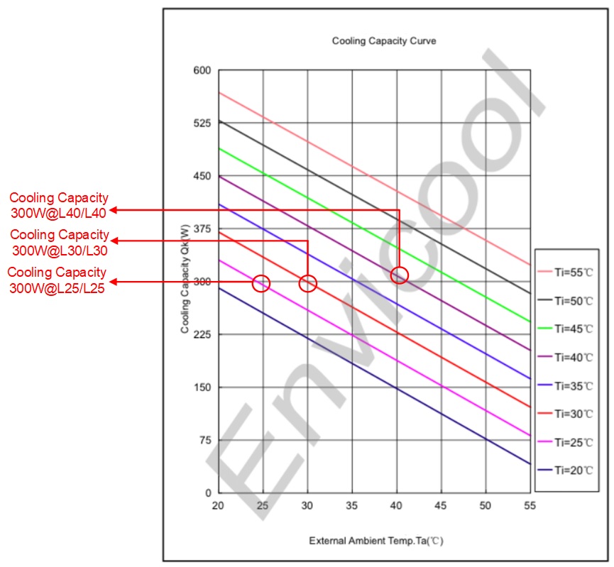
Cooling Capacity 300W with Different Temperature
If we look more deeply at the cooling capacity table above, we can find that the cooling capacity can actually reach 300W cooling capacity at different equivalent temperatures. For example, what we marked in the picture above:
(1) 300W@L25/L25
We can know from the figure that when the in cabinet temperature is 25℃ and the external ambient temperature is 25℃, the system can reach 300W.
(2) 300W@L35/L35
We can know from the figure that when the in cabinet temperature is 35℃ and the external ambient temperature is 35℃, the system can reach 300W.
(3) 300W@L40/L40
We can know from the figure that when the in cabinet temperature is 35℃ and the external ambient temperature is 35℃, the system can reach 300W.
We can find that when the in cabinet temperature and external ambient temperature are required to be consistent, the expected cooling capacity of 300W can be achieved.(Of course there are some additional costs, the power they consume is different, this will be discussed in detail in other articles)
However, we need to know that the above assumptions are very idealistic. In actual scenarios, the external ambient temperature will change with the environment. Then our previous idealized assumptions are no longer valid. This is often a scenario faced in actual deployment.
2.3 Equivalent Cooling Capacity Varies Due to Different Geographical Locations
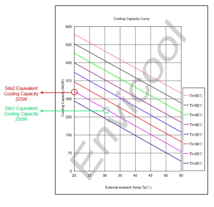
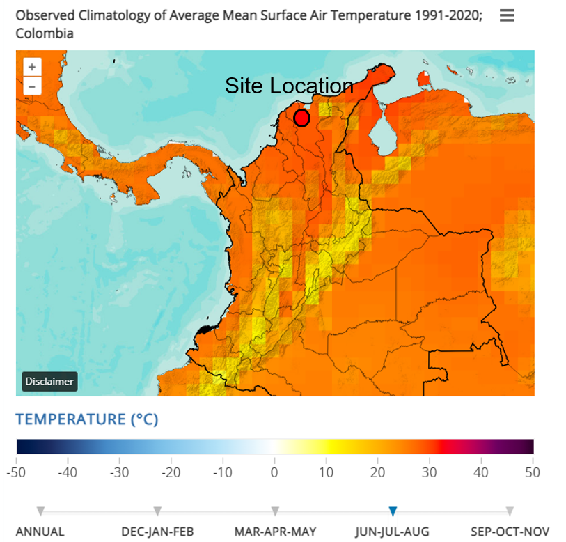
In actual deployment of outdoor telecom cabinet, the external ambient temperature will not be as ideal as imagined, and often varies depending on the site deployment location, thus affecting the equivalent cooling capacity of the air conditioner. Taking the country of Colombia as an example, we can find that different regions have different maximum temperatures in summer, which causes the equivalent cooling capacity of the same air conditioner to be different in different regions. As shown in the picture above, we have two sites, Site1 and Site2. It can be seen that the maximum temperature of Site1 is 32℃, and the maximum temperature of Site2 is about 20℃. Assume we use the same air conditioner used in the previous example, and assume the in cabinet temperature we set is 25℃. Then we can see the location of the equivalent cooling capacity from the figure below:
Equivalent Cooling Capacity for Site1 and Site2
According to the figure above, we can see that air conditioners with the same cooling capacity have different equivalent cooling capacities because different regions have different maximum ambient temperatures. Based on our example, we can find:
Site1 equivalent cooling capacity = 250W
Site2 equivalent cooling capacity = 325W
It can be found that the gap is not small. Therefore, we can draw an important conclusion. Air conditioners with the same capacity have different equivalent cooling capabilities because the maximum ambient temperature in the deployment area is different.
However, most suppliers and Carrier customers do not perform equivalent calculations on outdoor telecom cabinet cooling capacity due to differences in site location. In many cases, the configured air conditioner is only calculated based on the approximate heat dissipation of the equipment configured in the outdoor telecom cabinet. So suppose we have a DWDM project with the same configuration for each site, but the geographical location covers different areas of Colombia. Assuming we use the same air conditioning configuration, it may cause problems because the equivalent cooling capacity is different in different areas.
For more information about the above, you can also check out the following video:
3.Example of Calculating Cooling Capacity for Outdoor Telecom Cabinet
3.1 Assumption of Our Example
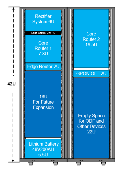
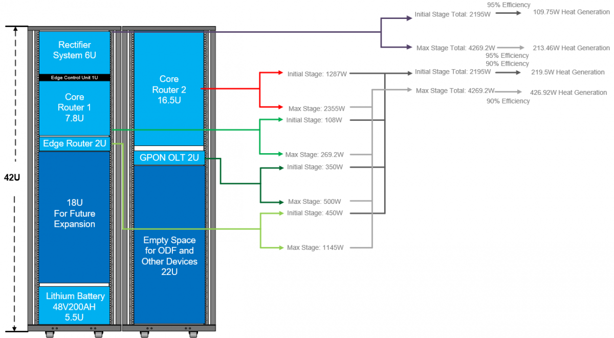
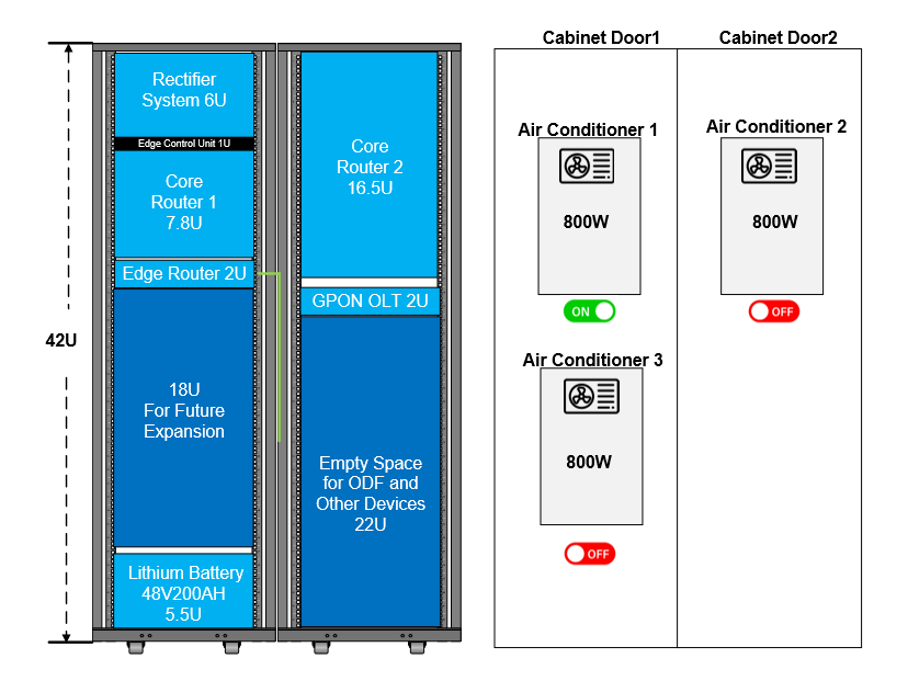
Example an Outdoor Telecom Cabinet Configuration
The above figure is a typical case, and we will use it as a reference to explain the considerations for cooling capacity calculation. This is a typical core site scenario. The customer has two core routers, one rectifier, GPON OLT, Edge Router and Lithium Battery. You can see that we have reserved some space for future expansion. To analyze this scenario, we first need to collect information about these devices from customers, especially the maximum power information of these devices.
Device
Initial Configuration Max Power
Expansion
Max Power
Efficiency
Quantity
Rectifier
6000W
6000W
96%
1
Core Router1
108W
269.2W
?
1
Core Router2
1287W
2355W
?
1
Edge Router
450W
1145W
?
1
GPON OLT
350W
500W
?
1
200AH Lithium Battery
NA
NA
NA
1
Max Power of Active Devices
The above is the information collection situation. Please note that when we configure an outdoor telecom cabinet and calculate the cooling capacity, we need to clarify the initial configuration and the final expansion configuration. Because in many cases, there is a big gap between the customer’s initial configuration and the maximum power expanded a few years later. These factors must be taken into account when initially configuring the outdoor telecom cabinet. Because once the air conditioner is configured in the outdoor telecom cabinet scenario, it is difficult to change or even expand the air conditioner again.
In addition, it is often difficult to clearly understand the efficiency of each device when communicating with customers. At this time, we can make some conservative assumptions. First, we need to understand that the efficiency of the device will greatly affect the heat generation of the entire system. Generally speaking, we can simply understand it as the following formula:
Heat = SystemMaxPower*(1-efficiency)
The above formula is not exactly correct, but we are only solving engineering problems, not theoretical research, so we can think of it as an approximation.From this we can know that the higher the power efficiency of the device, the less heat is converted from the maximum power. So when we know the system max power and efficiency, we can calculate the heat generation when the system is running.
However, this is an ideal state, but in reality it is difficult to collect the efficiency of all devices. Because this involves the situation of different manufacturers, some datasheets may not be complete. Some intentionally conceal this information. Based on these situations, we need to remind ourselves again that we are solving problems for customers in engineering, not doing theoretical research. Generally speaking, the overall efficiency of communication equipment will not be less than 90%, so we assume it is 90%. In addition, lithium batteries generally do not generate much heat, so we ignore it. The Rectifier will be calculated later. Then we can get the following table:
Device
Initial Configuration Max Power
Expansion Stage
Max Power
Efficiency
Initial Configuration Heat Generation
Expansion Stage
Heat Generation
Quantity
Core Router1
108W
269.2W
90%(We assume)
10.8W
26.92W
1
Core Router2
1287W
2355W
90%(We assume)
128.7W
23.55W
1
Edge Router
450W
1145W
90%(We assume)
45W
11.45W
1
GPON OLT
350W
500W
90%(We assume)
35W
50W
1
Total Power
2195W
4269.2W
Total Heat
219.5W
426.92W
Max Power and Heat Generation of System Load
Max Power and Heat Generation of System Load with Rack View
3.2 Rectifier Heat Generation
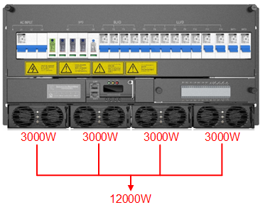
Max Power of Rectifier System
Heat Generation from Rectifier Explaination
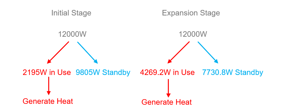
According to the explanation in the above figure, when the rectifier system is running, the used power will generate heat, while the other unused power will not generate heat (this statement is not accurate, but our goal is to calculate the final cooling capacity that needs to be configured in engineering, so we have made a certain degree of simplification). Therefore, we only need to calculate the heat generated by the rectifier based on the actual load’s max power.
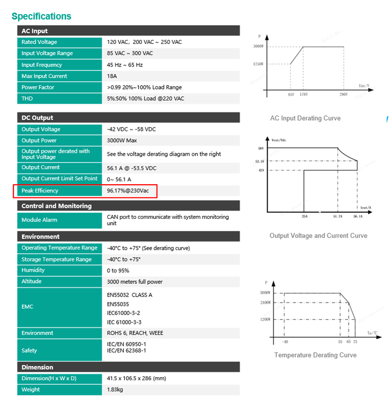
Check Rectifier Efficiency on Datasheet
The figure above shows the efficiency of the Edgeware Rectifier module. You can check this parameter based on the rectifier system of your project. Generally, manufacturers will write this parameter on the datasheet. Please note that we see that it is written as peak efficiency, but the actual operation will not always reach the peak efficiency. Therefore, we make a conservative estimate and assume that the efficiency of the rectifier system is 95%. Then we can calculate and determine the heat generation of the rectifier system based on the parameters determined in the previous article:
HeatRectifier = LoadPower*(1-Efficiency)
So according to the maximum power of the initial stage load of 2195W, we can calculate the Rectifier heat generation in the initial stage:
So we got number initial stage rectifer heat generation is 109.75W, in expansion stage is 213.46W. We will use this number in next step calculation.
Max Power and Heat Generation of System Load with Rack View Total
Now that we have calculated the heat generated by the entire system, we can start to calculate the required cooling capacity.
3.3 Cooling Capacity Calculation
3.3.1 Remember the Site Location Affects
Remember we explained the impact of the site’s geographical location on air conditioning performance(2.3 Equivalent Cooling Capacity Varies Due to Different Geographical Locations). We need to take this factor into account in this calculation example. Assume that our site location is as follows:
We can see that this site is located in a relatively hot area in Colombia. Assuming that the highest temperature in this area can reach 42°C in summer, this will greatly affect the performance of air conditioning in summer.
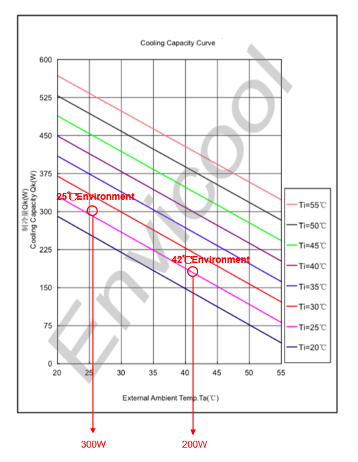
We use the 300W air conditioner performance curve mentioned above to make a rough judgment. At an ambient temperature of 25℃, the air conditioner’s cooling capacity is 300W, and at an ambient temperature of 42℃, its equivalent cooling capacity is 200W. Then we can roughly calculate the relationship between the following two:
200W/300W = 66.6%
So when the environment temperature is 42℃ , the air conditioning cooling capacity will drop to 66.6%. This conclusion will be used for our subsequent calculations.
3.3.2 Cooling Capacity Calculation
As we mentioned above, the maximum power of the initial stage is 2195W, and the expansion stage is 4269.2W. Also, don’t forget that we calculated in (3.2 Rectifier Heat Generation) that the heat generated by the rectifier under the initial stage load is 109.75W, and the heat generated under the expansion stage load is 213.46W. We summarize this information into the following table:
Device
Max Load
Heat Generation from Load
Heat Generation From Rectifier
Heat Total(Add
50% Safety Margin)
Initial Stage
2195W
219.5W
109.75W
(219.5W+109.75W)*150%=493.875W
Expansion Stage
4269.2W
426.92W
213.46W
(426.92W+213.46W)*150%=960.57W
Calculate Heat Generation with Adding Safty Margin
As you can see, in the table above, after calculating total heat generation, we added a 50% safety margin. This value is very subjective and can be adjusted based on your actual considerations. In general telecom scenarios, the CAPEX investment for air conditioning is much lower than the CAPEX of the entire site and its importance in the network. Therefore, in order to prevent various emergencies, it is very necessary to configure more cooling capacity than actually needed. After all, in a core site, even if you design 1+1 backup for all network devices and power systems, the damage of the air conditioner or the negligence in calculating the cooling capacity when expanding the site may cause the entire site to be unable to operate. After this step of calculation is completed, we need to calculate how large an air conditioner needs to be configured at an ambient temperature of 42°C. Please note that we have explained the derating of the equivalent cooling capacity of the air conditioner at 42°C in previous charpter (3.3.1 Remember the Site Location Affects), which is 66%. We can use this to proceed to the next step of calculation.
Device
Max Load
Heat Generation from Load
Heat Generation From Rectifier
Heat Total Generate
Cooling Capacity Needed in 42℃ Environment
Equivalent Cooling Capacity Needed in 25℃ Environment
Initial Stage
2195W
219.5W
109.75W
493.875W
493.875W
493.875W/66% ≈748.3W
Expansion Stage
4269.2W
426.92W
213.46W
960.57W
960.57W
960.57W/66% ≈1455.41W
Calculate Equivalent Cooling Capacity Needed
As calculated in the table above, first understand that the heat generation we calculated for the intial stage and expansion stage is 493.875W and 960.57W respectively. So if it is a cabinet without considering other conditions, the cooling capacity of the configured air conditioner must be greater than 493.875W in the intial stage and greater than 960.57W in the expansion stage. However, please note that our site is deployed in an environment that may reach 42℃ in the summer, which means that we must achieve a cooling capacity of 493.875W and 960.57W in an external environment of 42℃. We have previously calculated that the cooling capacity of the air conditioner in a 42℃ environment is derated to 66% of that in a 25℃ environment, and the air conditioners we purchased all refer to the capacity at 25℃ when marking their cooling capacity, so we can get the following:
In the table, we use this to calculate the final required cooling capacity. We can see that the initial stage requires 748.3W and 1455.41W.
3.4 Air Conditioner Selection and Configuration
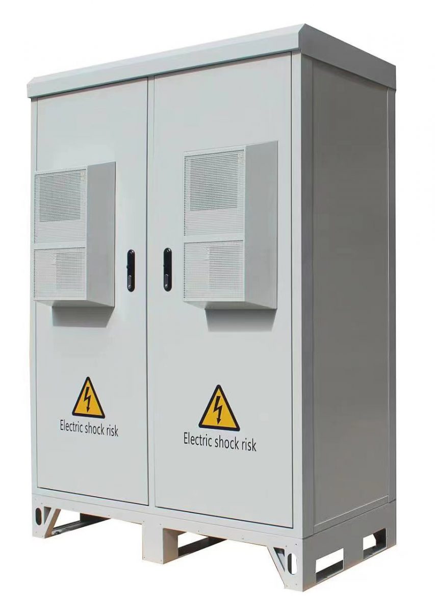
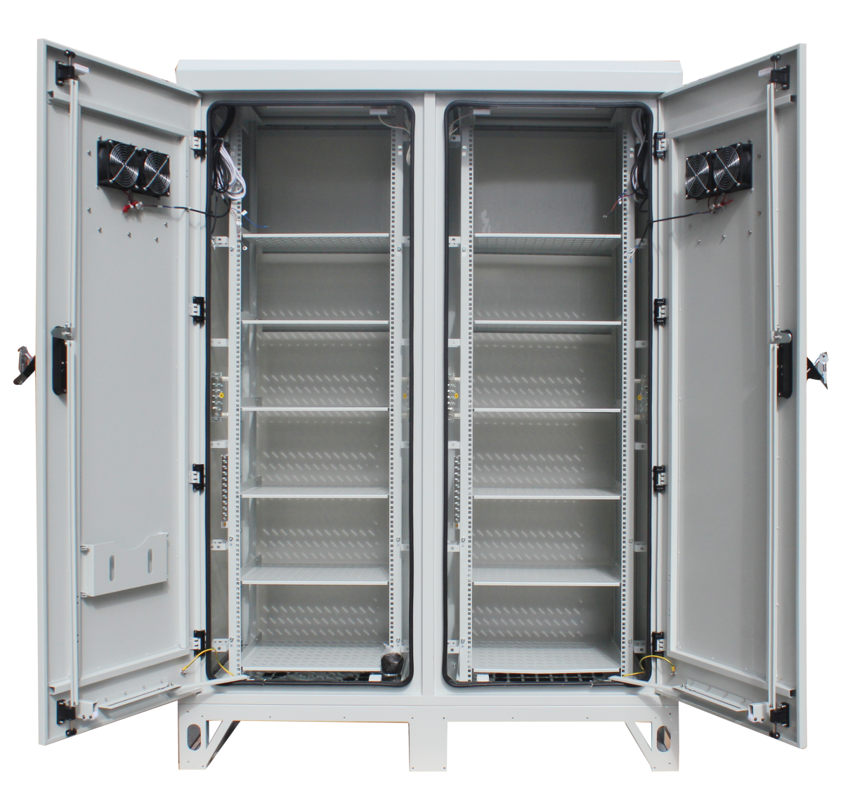
First of all, for the current cabinet configuration, we need two 42U Racks to meet the needs of equipment installation. We can choose Edgeware’s ST2200 series outdoor telecom cabinet to deploy. This is a dual cabinet system.
Edgeware ST2200 Outdoor Telecom Cabinet
In the previous section, we have made it clear that this outdoor telecom cabinet scenario requires an air conditioner with a cooling capacity greater than 748.3W in the initial stage and an air conditioner with a cooling capacity greater than 1455.41W in the expansion stage. Please note that we can of course configure an air conditioner with a cooling capacity of 1600W to meet the needs of the expansion stage, but the problem is that when the deployment is in the initial stage, we only need 748.3W, so a lot of cooling capacity is wasted. And this wasted electricity will greatly increase the site’s OPEX after a long period of operation. Therefore, we do not recommend configue a big air condtioner to complex the final expansion stage request.
Recommended Air Conditioner Configuration
As you can see, we have configured three air conditioners, each with 800W. One of them is turned on in the initial stage, so it only meets the cooling needs of the first step in the initial stage. In the expansion stage, we turn on the second one, which is in standby mode before that. The third one is configured as a backup, thus achieving the need for N+1 backup of the entire machine. In this way, we can save electricity to the greatest extent while ensuring the needs of capacity expansion and high reliability of the entire system.
Of course, you will find that in this scenario, we need to turn on the corresponding air conditioner according to the power of the load. Or turn on the backup air conditioner under certain conditions. But after we have deployed the site, these sites are usually in the rural area, and it is not easy to maintain the site. At this time, Edgeware’s power management and cooling management system is needed.
4.Edgeware Power Management and Cooling Management System
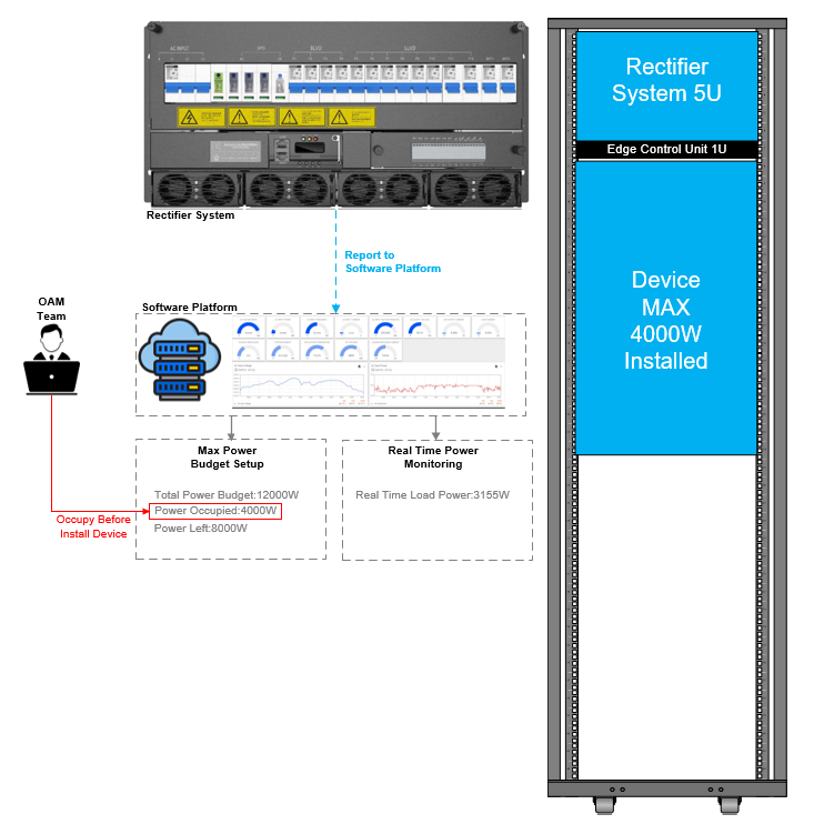
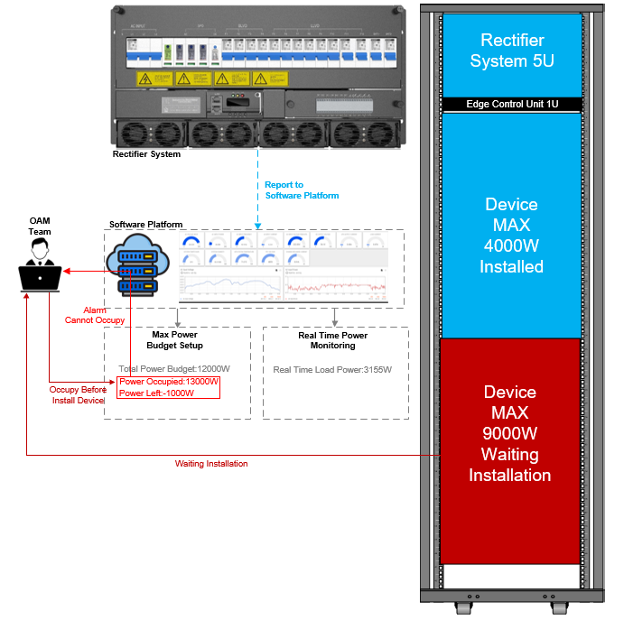
4.1 Power Management and Occupation
Power Occupation Successful
Power Occupation Failed
4.2 Cooling Management System
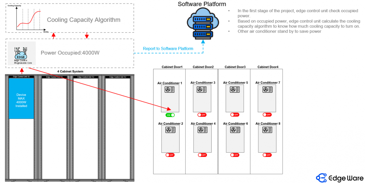
Edgeware Cooling Management System Auto Calculation and Turn On Air Conditioner-First Stage
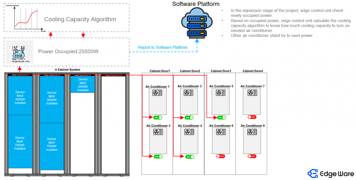
Edgeware Cooling Management System Auto Calculatin and Turn On Air Conditioner-Expansion Stage
The Cooling Management System developed by Edgeware works closely with the power management system. Based on the power occupation indicated by the power management, the system can automatically calculate the air conditioning situation that needs to be turned on. The air conditioners that are not turned on are in stand by state, the compressor is turned off, and only the CPU control system remains turned on, thereby saving energy to the greatest extent.
5.Summary
How to Calculate Cooling Capacity for Outdoor Telecom Cabinet is a systematic problem that requires consideration of many factors. When designing the scenario, please be sure to consider the load, power system, maximum outdoor temperature and other factors, and leave a safety margin to achieve stable operation of the outdoor telecom cabinet, reduce failure rate, and reduce OPEX. If you need a deeper understanding, please contact Edgeware. We will conduct in-depth design and consultation based on your scenario to find the best solution.